| Question:
I recently heard about the launch of the
coaxial watch. Could you explain its mechanism and why it is so revolutionary in the
mechanical watch?
Mark Enderby, Glasgow, Scotland
 Early escapements Early escapements
There have been hundreds of different types of escapements created over the years but
many were produced only as a single prototype or in a very limited series and thus quickly
fell into oblivion. Others had a somewhat longer existence but were eventually abandoned
because of difficulties in fabrication or because of their mediocre performance. To this
day, we can affirm that only five escapements have been produced in fairly large
quantities and which have endured during a reasonably long period of time. The first one
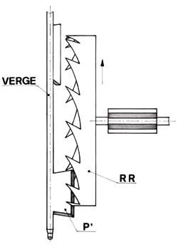
was the verge escapement (sometimes called the crown-wheel escapement). It can be
considered the granddaddy of them all, since it was used uninterruptedly in both clocks
and watches from the origins of mechanical horology in the early 1300s all the way up to
the middle of the 19th century (Figures 1a & 1b).
 |
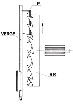 |
| Figures 1a & 1b: Verge or
crown-wheel escapement. The crown wheel acts alternatively on the upper and lower pallets
of the arbor, which itself serves as the balance staff. |
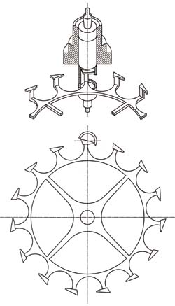
Beginning in about 1720, however, the cylinder esca-pement began to give this device some
strong competition. Invented by the great English clock maker, George Graham, the cylinder
escapement was used to equip thousands of watches until the early 1950s. It was also the
preferred escapement of the gifted French horologer Ferdinand Berthoud (1727-1807), one of
the creators of marine timekeepers during the end of the 18th century (Figure 2). The
world's centre for the production of this escapement was in the Haut-Doubs in the
Franche-Cont region of France near the Swiss border.
During the same period, the Duplex escapement, although probably invented in France, was
used primarily in England.
 |
 |
| View of a cylinder escapement. |
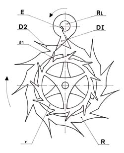
Figure 3: Duplex escapement. The two coaxial wheels
turn in the direction of the arrow. The largest is in its locked position against the
balance staff. |
Better, but more delicate than the cylinder escapement, this device is interesting in
light of the new Omega innovation. In fact, the Duplex escapement possessed two
superimposed and concentric wheels. The larger one assured the locking or rest position
while the smaller one provided the impulse (Figure 3). The current coaxial escapement uses
a part of this device.

 Major drawbacks Major drawbacks
The three escapements discussed above all had one large drawback that caused them to
be eventually abandoned. Their escape wheel reached its locking position by pushing
directly on the balance staff in such a way that the oscillations were constantly
disturbed, with the result that the timing adjustment of the watch was seriously affected.
Finally, horologers realized that it they were to obtain good adjustments, it was
imperative that they create a system whereby the balance could oscillate freely.
Since ships on the high seas needed the right time to be able to navigate correctly, clock
makers dedicated much research on creating esca-pements where the escape wheel came to
rest, not on the balance staff, but on an intermediate part, independent of it.

 Lever escapement Lever escapement
Towards 1760, simultaneously in France and in England, two horologers succeeded in
creating the first detached escapements. The lever escapement was the invention of the
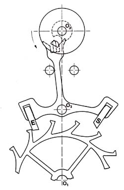
Englishman, Thomas Mudge (1715-1794). In its current form, it is shown in Figure 4. The
wheel comes to rest on an intermediate part called the lever. In French, it is called
ancre (anchor) because it looks vaguely like a boat anchor. The balance causes the release
of the wheel by means of a pin that enters a fork attached to the lever. It receives a
small quantity of energy that is sufficient to maintain the oscillations due to the wheel
sliding over the inclined faces of the lever as soon as it is released from its locked
position. The lever provides both the locking position and the impulse. The simplicity of
this system, combined with its dependability, has resulted in its use in nearly all
mechanical watches. It should be mentioned, however, that the rather unnatural movement of
the entry pallet, E, (Figure 4) produces an engaging friction, requiring that the teeth of
the wheel be lubricated. Also, the trans-mission of energy to the balance by the lever and
fork is less efficient than the direct action of the wheel on the balance.
 |
 |
| Figure 4: Lever escapement. The escape wheel
is locked alternatively against the pallets E or S. |
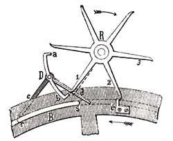
Figure 5: Detached escapement. Designed by
Pierre Leroy, this escapement uses elements of the lever escapement for the locked or
unlocked positions, and the detent escapement for the impulse. |

 Detent escapement Detent escapement
In 1764, the French horologer Pierre Leroy (1717-1785) constructed a marine watch
equipped with an escapement detached from his invention (Figure 5). This was a marriage
between Mudge's lever escapement and one that would later become the detent escapement,
providing direct impulses. The lever, D, with its pallets, A and B, provided the locking
position of the wheel, while the latter gave the direct impulse to the balance via the
catch, E. In its early existence, improvements in this type of escapement were carried out
by Ferdinand Berthoud. Later, the London clockmakers, John Arnold (1736-1799) and Thomas
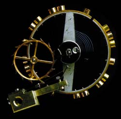
Earnshaw (1749-1829), made changes which resulted in its current form (Figure 6).
The detent escapement is still used in marine chronometers today. It is, without a doubt,
the most efficient escapement although this has never been formally proven. Other small
advantages of this device, which are beyond the scope of the article, make it a very
interesting escapement for use in precision chronometry. The wheel is locked against a
long detent spring, while the impulse is provided by the table roller fitted to the
balance staff.
The detent escapement is sensitive to movements or shocks and does not always maintain its
locking position very successfully. It impulses in only one direction and can accidentally
move past two teeth at a time during each vibration when the amplitude is too large. This
phenomenon is called tripping. The detent escapement will not start again by itself. If
the watch stops because it is wound down, it will not begin on its own once it has been
wound up and needs to be shaken a bit to get it started. The great advantage of this type
of escapement, however, is that it does not require lubrication.
 |
 |
| Figure 6: Detent escapement. The locking
position occurs against the detent spring. The impulse is direct, but in one direction on
the pallet, N, placed on the table roller that is concentrically attached to the balance
staff. |
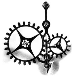
Figure 7: The natural escapement as
conceived by Abraham-Louis Breguet. |
Understanding the advantages and disadvantages of the lever and detent escapements, one
can be greatly tempted to imagine a single escapement that combines the advantages of both
systems without their drawbacks. This is exactly what the talented English watchmaker,
George Daniels has done with his coaxial escapement for the brand Omega. Before going into
more detail about the current device, lets look at what has been done in this same
direction over the last two centuries.

 Breguet's contribution Breguet's contribution
It should be no surprise to find the name of Abraham-Louis Breguet (1747-1823) linked
to this type of escapement system. His first realization in this regard was his natural
escapement in which the oscillations of the balance were maintained by direct impulses,
which were given by two escape wheels acting alternatively on two small wings attached to
the balance staff (Figure 7). The first wheel was turned by the fourth wheel acting on its
pinion, while the second wheel was geared to the first.
The escape wheels, in their locked position against the pallet mounted on the fork, were
freed at each turn of the roller-pin placed on the table roller of the balance, which
worked with the fork, as in the case of the lever escapement. The direct impulses occurred
in a natural way thus giving rise to the name of this system. Breguet's new escapement
could also function without the need for oil. The gain in energy in relation to the lever
escapement system is deceptive because of the gearing ratio of the two wheels and the sum
of their inertia. Since he very quickly recognized its limitations. Breguet used this type
of escapement very little.
 |
 |
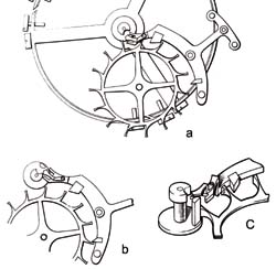
| Figures 8: The lever escapement and detent
escapement as designed by Breguet. The direct impulse is transferred from the wheel to the
impulse pin of the table roller. |
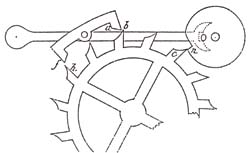
Figure 9: The lever escapement and detent
escapement as designed by Bise. The direct impulse is made on the catch, n, of the table
roller. |
A drawing on page 320 of the book The Art of Breguet by George Daniels, depicts an
escapement that Breguet realized around 1820 (Figure 8a). Here, one escape wheel ensures
the functions of the locking position and the impulse, as in the lever escapement, but the
entry pallet only serves to lock the wheel (Figure 8b). As soon as this wheel is released
by the action of the balance and fork, it directly impulses the pin of the table roller
without involving the lever (Figure 8c). The impulse given by the exit pallet is the same
as in the lever escapement. This system combines the lever and detent mechanisms and has
been copied and reinvented a number of times over the years. The remarkable watchmaker
(and editor) Joseph Flores* cites seven watchmakers who have exploited Breguet's idea.

 Other ideas Other ideas
Around 1860, or forty years after Breguet, an abbot and horologer by the name of Bise
presented an escapement functioning exactly on the same principles as the one created by
Breguet (Figure 9). The direct impulse is given using a catch on the table roller rather
than a pin. This is the only difference of any importance. In 1860, La Revue
Chronométrique of Claudius Saunier recorded a debate between Abbot Bise and a certain Mr.
Racap who claimed to have constructed the very same escapement in 1853.
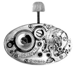
Joseph Flores also writes that a watchmaker named Jules Pellaton from Bienne filed a Swiss
patent, Number 101849, on November 16, 1923 using a similar mechanism. Pellaton also
believed that he was the first to have invented this type of escapement and used it in one
of his oval ladies' wristwatches (Calibre AS 610, Figures 10).
 |
 |
| Figure 10: Pellaton's oval Calibre AS 610 as
it is mounted in a watch. |
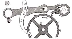
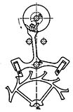
Figure 11: A coaxial lever and detent
escapement from the beginning of the 20th Century. |
To end this review of earlier escapements, we must mention another system that resembled
even more closely that of George Daniels recent invention since it too was a coaxial
escapement, which provided the same functions (Figure 11). However, it had a single escape
wheel, but one series of teeth were placed on the circumference while a second series of
teeth were located on the surface of the wheel. The outside teeth were locked in position,
D, against a small block attached to the fork. They provided direct impulses, while the
inside teeth worked with the lever by acting on its only pallet. Unfortunately, the
arrangement left much to be desired. In this escapement, as in all those that we have
discussed, the tooth of the wheel slid over the impulse face with a great deal of
friction, thus requiring frequent oiling. As can be imagined, it was never a very great
threat to the already well-established lever escapement. Charles Gros*, in his excellent
book, Echappements d'hor-loges et de montres, makes the following remark about this early
mechanism: 'This escapement is ingenious but it is more complicated than a lever
escapement and offers no advantages over the latter. In addition, it requires a very high
level of precision if one wishes to obtain good operation.'

 Enter George Daniels Enter George Daniels
As far as the basic functions go, the coaxial escapement created by George Daniels
does not significantly differ from those models discussed above, namely a direct impulse
by the table roller of the balance and an indirect impulse by the fork on the impulse pin.
However, Dr. Daniels deserves a great deal of credit for understanding how to optimise the
functions of this escapement in order to obtain a level of efficiency superior to that of
the lever escapement while preserving the reliability of the latter.
He succeeded in greatly minimising the sliding friction by completely separating the
functions of locking and impulsion. To this end, the lever has three pallets. The two
lateral pallets, F and H, are used for the locking and unlocking positions. The central
pallet, G, receives the impulse via the pinion of the escape wheel, C, which acts as the
second escape wheel. The wheel, D, ensures the locked position alternatively on the
pallets F and H and also gives a direct impulse on the pallet, J, on the table roller of
the balance. The pin, L, works with the fork to release the locked wheel and receive the
indirect impulse.
The position of the central pallet in relation to one of the teeth of pinion, C, ensures a
quasi-tangential impulse with very little friction. None of the earlier escapements
offered this same advantage. Besides the gain in force transmitted, the arrangement of the
various elements in this escapement allows it to function without oil.

 Advantages and disadvantages Advantages and disadvantages
The principal advantage of the coaxial escapement is the transmission of force in a
quasi-tangential manner, which minimises the losses due to friction, reduces wear and
tear, and eliminates the need for lubricating the escapement. There is greater stability
in the timing adjustment and consequently a significantly higher level of reliability. The
efficiency registered is 28% for this system while it is 25% for the lever escapement. The
gain in energy transmitted is therefore on the order of 10% to 12%.
The disadvantages of this innovative system are its higher costs and the need for a very
high level of precision in the manufacture of its component parts and their assembly. Each
measurement must be rigorously respected and nothing can be modified during assembly. This
level of exactness is normally only possible in those enterprises with very sophisticated
equipment and experience. The need for an intermediate wheel between the fourth wheel and
the escape wheel also increases the price, as well as also slightly reducing the systems
efficiency. Finally, if, contrary to expectations, it becomes necessary to add
lubrication, the oil from the teeth of the pinion might spread to the gear of the
intermediate wheel which would be very undesirable.
In conclusion, Omega should be congratulated for having taken the bold and necessary steps
along the road of innovation in an area that up to this time had seemed untouchable. 
*Authors
note: Much of the information in this article on early escapements was taken from the book
by Charles Gros, entitled, Echappements d'hor-loges et de montres, and from the remarkable
work of watchmaker and editor Joseph Flores, much of which has appeared in various issues
of the Revue de l'Association Française des Amateurs d'Horlogerie Ancienne, of which
Flores is the principal editor. The author would especially like to thank Mr. Flores for
his help and the kind use of his photographs to illustrate this article. |
 PRECISION WATCH REPAIR BY CHARLIE SQUIRES